3.4.5-packet-trunk-configuration
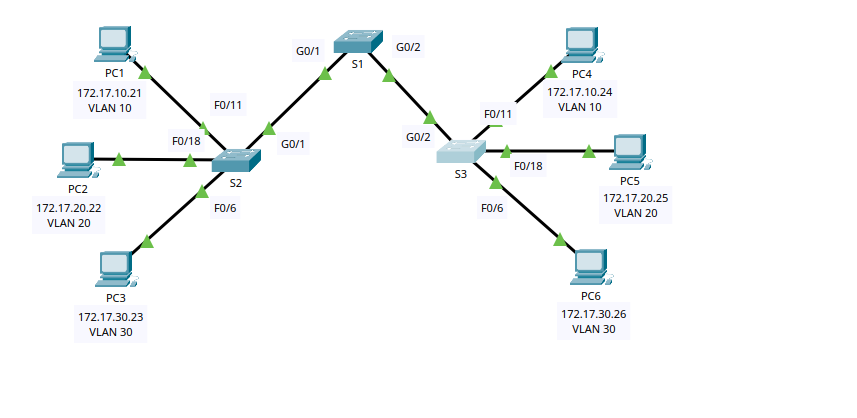
This lab focuses on creating and naming VLANs, assigning access ports to the correct VLANs, and configuring trunk links between switches using VLAN 99 as the native VLAN. It also includes a Voice VLAN (150) on a port connected to an IP phone and a PC, with QoS trust enabled for voice traffic.
VLANs Used in This Lab
VLAN 10: Facultad/Personal
VLAN 20: Students
VLAN 30: Guest
VLAN 99: Management&Native (Native VLAN on trunks)
VLAN 150: VOICE
1) Switch S2 Configuration
1.1 Create and Name VLANs
enable
configure terminal

vlan 10
 name Facultad/Personal
vlan 20
 name Students
vlan 30
 name Guest
vlan 99
 name Management&Native
vlan 150
 name VOICE

end
Why:
VLANs logically segment the network into separate broadcast domains.
VLAN 99 is used as the native VLAN (untagged traffic) on trunk links.
VLAN 150 is reserved for voice traffic from IP phones.
1.2 Assign Access Ports to VLANs
Port assignments:
Fa0/11 → VLAN 10
Fa0/18 → VLAN 20
Fa0/6 → VLAN 30
configure terminal

interface f0/11
 switchport mode access
 switchport access vlan 10
exit

interface f0/18
 switchport mode access
 switchport access vlan 20
exit

interface f0/6
 switchport mode access
 switchport access vlan 30
end
Why:
- End devices (PCs, printers) should be connected to access ports, which carry traffic for only one VLAN.
1.3 Configure Trunk to S1 (G0/1)
configure terminal
interface g0/1
 switchport mode trunk
 switchport trunk native vlan 99
end
Why:
Trunk links carry multiple VLANs between switches.
Setting the native VLAN to 99 ensures untagged traffic is placed in VLAN 99.
2) Switch S3 Configuration
2.1 Create and Name VLANs
enable
configure terminal

vlan 10
 name Facultad/Personal
vlan 20
 name Students
vlan 30
 name Guest
vlan 99
 name Management&Native
vlan 150
 name VOICE

end
2.2 Assign Access Ports (Standard VLAN Ports)
Port assignments:
Fa0/18 → VLAN 20
Fa0/6 → VLAN 30
configure terminal

interface f0/18
 switchport mode access
 switchport access vlan 20
exit

interface f0/6
 switchport mode access
 switchport access vlan 30
end
2.3 Configure Voice + Data Port (Fa0/11)
Fa0/11 connects to an IP phone and a PC behind it:
PC data traffic must be VLAN 10
Phone voice traffic must be VLAN 150
QoS must trust CoS values from the phone
configure terminal
interface f0/11
 switchport mode access
 switchport access vlan 10
 mls qos trust cos
 switchport voice vlan 150
end
Why:
switchport access vlan 10keeps the PC in the data VLAN.switchport voice vlan 150places the phone voice traffic into the voice VLAN.mls qos trust cosallows the switch to prioritize voice traffic based on CoS markings from the IP phone.
2.4 Configure Trunk to S1 (G0/2)
configure terminal
interface g0/2
 switchport mode trunk
 switchport trunk native vlan 99
end
3) Switch S1 Configuration
3.1 Create and Name VLANs
enable
configure terminal

vlan 10
 name Facultad/Personal
vlan 20
 name Students
vlan 30
 name Guest
vlan 99
 name Management&Native
vlan 150
 name VOICE

end
3.2 Configure Trunks (G0/1 and G0/2)
S1 trunks connect to S2 and S3, using VLAN 99 as native on both links:
configure terminal
interface range g0/1 - 2
 switchport mode trunk
 switchport trunk native vlan 99
end
Why:
S1 is the central switch linking S2 and S3.
Both trunk links must use the same native VLAN to avoid mismatch issues.
Verification Commands (Recommended)
Run these on each switch to confirm VLAN and trunk status:
show vlan brief
show interfaces trunk
show interface f0/11 switchport
Expected results:
VLANs 10, 20, 30, 99, and 150 exist on all switches.
Trunks show as trunking on the correct gigabit interfaces.
Native VLAN on trunks is 99.